Grid Parabolic Antennas
Military Grade L and C Band Grid Parabolic Antennas
High-gain grid parabolic antennas for data link terminals and point-to-point links. Designed for rugged, reliable operation in extreme conditions where commercial antennas may fail.
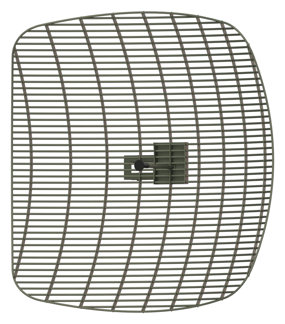
High gain, low wind load, built to last
SkyBeam grid parabolic antennas concentrate the signal into a narrow beam for long range, high-quality links between the ground and the aircraft, or between two ground sites. The open grid reflector lets the wind pass through, so the antenna stays stable and light even in storm-force winds.
A 97 cm L-band model covers 1.30–1.50 GHz with dual polarisation and three C-band sizes cover 4.40–5.85 GHz with 25 to 32 dBi gain. All models are designed to MIL-STD-810H environmental requirements and can be supplied in military colours such as RAL 6031 or TAN 686.
Need the antenna to follow a moving aircraft? See our Ground Tracking Antenna System.
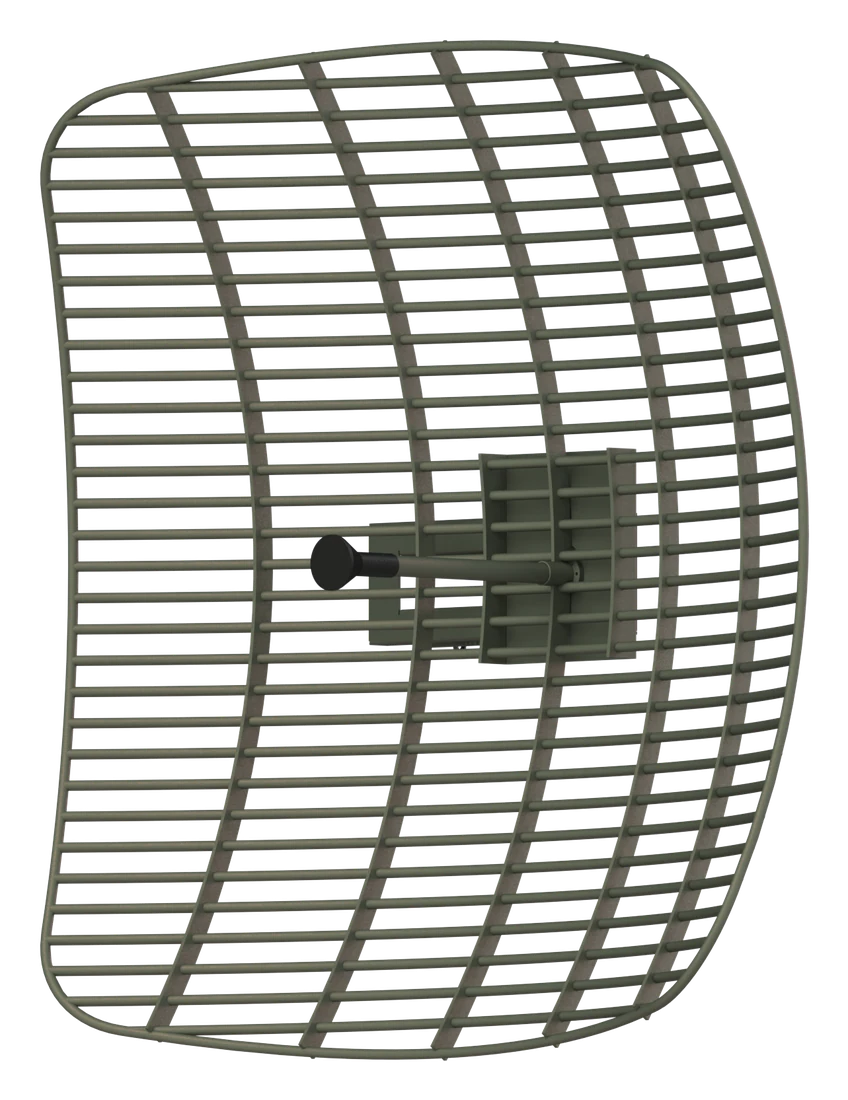
Engineered for the field
High gain and efficiency
Up to 32 dBi and a narrow beam for long range links, with front-to-back ratio above 30 dB (C-band).
Low wind load
The open grid reflector survives winds of 130 to 200 km/h depending on the model.
Rugged and lightweight
Military grade construction from 2.5 kg, operating from -40 °C up to +85 °C (C-band).
Adjustable polarisation
The L-band model is dual polarised (V and H); C-band models have manually adjustable linear polarisation.
Easy pole mounting
Pole mount brackets for a range of pole diameters, quick to install and align.
Lightning protection
DC-short feed on all models protects connected equipment.
MIL-STD-810H design
Temperature, vibration, shock, humidity, salt fog and rain requirements.
Colour and interface options
RAL 6031, TAN 686 or custom colours; other connectors and mounts on request.
Choose the size for your link
Larger reflectors give more gain and a narrower beam for longer range; smaller ones are lighter and easier to deploy.
- Beamwidth
- 15°
- Size
- 970 × 970 × 380 mm
- Weight
- ~7.5 kg
- Wind load
- 130 km/h
- Beamwidth
- 5°
- Size
- 610 × 610 × 360 mm
- Weight
- 2.5 kg
- Wind load
- 200 km/h
- Beamwidth
- 3–4°
- Size
- 970 × 970 × 335 mm
- Weight
- ~6 kg
- Wind load
- 180 km/h
- Beamwidth
- 1.3–1.5°
- Size
- 1440 × 1440 × 425 mm
- Weight
- ~13 kg
- Wind load
- 180 km/h
Specifications
| CGA100S1400M97 cm · L-band | CGA60S4400M60 cm · C-band | CGA100S4400M97 cm · C-band | CGA140S4400M144 cm · C-band | |
|---|---|---|---|---|
| Frequency range | 1.30 – 1.50 GHz | 4.40 – 5.85 GHz | 4.40 – 5.85 GHz | 4.40 – 5.85 GHz |
| Gain (typ.) | 20 dBi | 25 dBi | 30 dBi | 32 dBi |
| Beamwidth (HPBW) | 15° | 5° | 3 – 4° | 1.3 – 1.5° |
| Polarisation | Dual (V and H) | Linear, adjustable | Linear, adjustable | Linear, adjustable |
| VSWR | < 2:1 | < 2:1 | < 2:1 | < 2:1 |
| Cross polarisation | > 25 dB | > 25 dB | > 25 dB | > 25 dB |
| Front-to-back ratio | > 25 dB | > 30 dB | > 30 dB | > 30 dB |
| Impedance | 50 Ω | 50 Ω | 50 Ω | 50 Ω |
| Connector | N-type female* | N-type female* | N-type female* | N-type female* |
| Lightning protection | DC-short | DC-short | DC-short | DC-short |
| Dimensions | 970 × 970 × 380 mm | 610 × 610 × 360 mm | 970 × 970 × 335 mm | 1440 × 1440 × 425 mm |
| Weight | ~7.5 kg | 2.5 kg | ~6 kg | ~13 kg |
| Operating temperature | -40 °C to +51 °C | -40 °C to +85 °C | -40 °C to +85 °C | -40 °C to +85 °C |
| Wind load endurance | 130 km/h | 200 km/h | 180 km/h | 180 km/h |
| Mounting | Pole, Ø60 mm* | Pole, Ø100 – 150 mm* | Pole, Ø60 mm* | Pole, Ø60 mm* |
| Colour | RAL 6031* | RAL 6031* | RAL 6031* | RAL 6031* |
* Other options available. Environmental design: MIL-STD-810H low and high temperature, vibration, shock, humidity, salt fog and rain. Specifications are subject to change without notice.
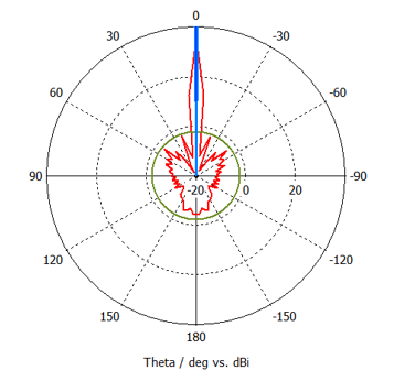
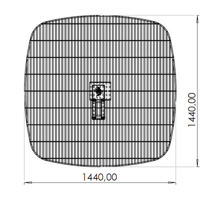
Verified by measurement
Every design is measured before release. Example: 144 cm C-band model.
Where they are used
UAV ground control stations
Fixed high-gain antenna for data link and video reception at the ground control station.
Point-to-point links
Long range links between ground sites, relay stations and command posts.
Military radio relay
Fixed, tactical and vehicle-mounted radio relay links in the 4.4–5.0 GHz military band.
Surveillance network backhaul
Data links from camera and radar sites along borders, coastlines and critical facilities.
Mobile command posts
Quick setup on a vehicle or mast, where low weight and low wind load make deployment easier.
Need a grid antenna for your link?
Tell us your frequency, range and mounting needs. We will recommend a model or a custom version.
Tell us about your platform and requirements. Our engineers will get back to you.
Your request has been received. Our team will get back to you shortly.
We have sent the datasheet to . It should arrive within a few minutes. If you do not see it, please check your spam folder.